
Portál AbcLinuxu, 25. dubna 2024 00:28
25.10.2019 07:13
| Přečteno: 4534×
|
 . Well, not exactly waited. I've managed during these 2 years to make a botched "vanilla" kernel from openwrt patches, which is used on the default Vocore2. I've got some time in the summer of 2018, so I could start hacking my project(s).
Have you ever tried to develop a low level stuff, for example a PCIe driver? Or even better! A PCIe controller on FPGA? You can probably guess there will be many crashes and system restarts. For a PC machine it means long reboot and possible data corruption (when I was playing with SunPCI IIpro I've actually managed to destroy a PIII based motherboard ... it was a BXcel one, so not a big deal though :-P ). For an embedded machine with read-only rootfs there isn't any problem to restart in a few seconds. So ... let's make an embedded testing platform for PCIe cards.
. Well, not exactly waited. I've managed during these 2 years to make a botched "vanilla" kernel from openwrt patches, which is used on the default Vocore2. I've got some time in the summer of 2018, so I could start hacking my project(s).
Have you ever tried to develop a low level stuff, for example a PCIe driver? Or even better! A PCIe controller on FPGA? You can probably guess there will be many crashes and system restarts. For a PC machine it means long reboot and possible data corruption (when I was playing with SunPCI IIpro I've actually managed to destroy a PIII based motherboard ... it was a BXcel one, so not a big deal though :-P ). For an embedded machine with read-only rootfs there isn't any problem to restart in a few seconds. So ... let's make an embedded testing platform for PCIe cards.
-mips16 (the instructions are only 2 bytes/16 bits long)-mdsp with DSP extensions for vector operations (four 8bit values in one 32bit word), saturation, etc. )
) ). But still 256 kB of SRAM L2 cache should be fine (we will see the impact of a small cache to the applications later).
). However the existing datasheet is not a single requirement, a poor quality datasheet means problems. There doesn't seem to be a datasheet available directly from mediatek website, but there was one somewhere on the internet and the creator of Vocore2 has one available (good!).
After meddling with some MT7628's controllers (rewriting interrupt routine of ethernet driver, trying to get SDHC controller working, controlling PCIe in bash, ...) I'm marking the datasheet as under average/just enough sufficient. The controllers are better quality than controllers of Intel PXA, but the documentation is incomplete and brief (Intel PXA27x is better documented), even a Microchip PIC24 MCU has a better clock distribution diagrams! Some controllers like ethernet have only the register description and no other info. There are DMA descriptors and its fields aren't even described. I've had to extrapolate the information from datasheets of two different Mediatek + Ralink SoCs, where the ethernet section had a better documentation (other sections were less documented though). The problem is the other chips have some differences in the ethernet controller (different fields in the descriptors).
The biggest problem is the PCIe controller. I've managed to find out the core is most likely a DesignWare Core from Synopsys and Mediatek is using these cores in different SoC series with some considerable implementation variations. There is a matching driver for MT7628 in the vanilla kernel arch/mips/pci/pci-mt7620.c, but it doesn't work very well. Interestingly there are drivers for other SoCs from Mediatek/Ralink, which seems to be almost compatible with MT7628. Maybe they will be joined together in the future. There is even a general DesignWare Core driver in drivers/pci/controller/dwc, but the register access in MT7628 is done in a different and incompatible way. It even looks like the MT7628 PCIe could be a stripped down PCIe controller from the other Mediatek chips. The MT7628 datasheet contains some leftovers from previous chip generation. For example a note like "this register is valid only in device mode
). But still 256 kB of SRAM L2 cache should be fine (we will see the impact of a small cache to the applications later).
). However the existing datasheet is not a single requirement, a poor quality datasheet means problems. There doesn't seem to be a datasheet available directly from mediatek website, but there was one somewhere on the internet and the creator of Vocore2 has one available (good!).
After meddling with some MT7628's controllers (rewriting interrupt routine of ethernet driver, trying to get SDHC controller working, controlling PCIe in bash, ...) I'm marking the datasheet as under average/just enough sufficient. The controllers are better quality than controllers of Intel PXA, but the documentation is incomplete and brief (Intel PXA27x is better documented), even a Microchip PIC24 MCU has a better clock distribution diagrams! Some controllers like ethernet have only the register description and no other info. There are DMA descriptors and its fields aren't even described. I've had to extrapolate the information from datasheets of two different Mediatek + Ralink SoCs, where the ethernet section had a better documentation (other sections were less documented though). The problem is the other chips have some differences in the ethernet controller (different fields in the descriptors).
The biggest problem is the PCIe controller. I've managed to find out the core is most likely a DesignWare Core from Synopsys and Mediatek is using these cores in different SoC series with some considerable implementation variations. There is a matching driver for MT7628 in the vanilla kernel arch/mips/pci/pci-mt7620.c, but it doesn't work very well. Interestingly there are drivers for other SoCs from Mediatek/Ralink, which seems to be almost compatible with MT7628. Maybe they will be joined together in the future. There is even a general DesignWare Core driver in drivers/pci/controller/dwc, but the register access in MT7628 is done in a different and incompatible way. It even looks like the MT7628 PCIe could be a stripped down PCIe controller from the other Mediatek chips. The MT7628 datasheet contains some leftovers from previous chip generation. For example a note like "this register is valid only in device mode PCIE_RC_MODE", but there is no device mode description nor settings anywhere. For example, the subdevice VID/DID register, which is used only in PCIe endpoint device, can be filled only after a flag is switched.
The flag is documented only in older MT7620, which declares PCIe device support. But still in MT7628 there is a default subdevice ID value 0x7628 (someone had to do the work and rewrote the number in HDL!). The default PCI VID, DID and class registers are filled with values for mediatek wifi card (MT7620 can be turned into a "smart" PCIe wifi card). Finally the DW core can be synthetised with an ability to switch between device/host, but there is no indication this configuration was used (I would say it is). The MT7620's PCIe can switched with the SYSCFG1 register, bit 8 PCIE_RC_MODE (0 = device, 1 = host), on MT7628 the switch is located at the same place in SYSCFG1 register (0x10000014) and it activates the PCIE0_SUBID register (0x10142038), but the functionality of the configuration must be yet tested (it can be some kind of remains from the HDL code of the MT7628 development). If the device mode works correctly you could point PCIe space to the addresses of the controllers and you could use vocore2 as PCIe ethernet, USB, SPI, SDHC, wifi and/or sound host card.
BTW a warning from the future: the default/powerup values of VID/DID/class will make you suffer  .
.
| Bits | Flag | Description |
|---|---|---|
| 27:24 | P2P_BR_DEVNUM2 | Device number setting of Virtual PCI-PCI bridge #2 |
| 23:20 | P2P_BR_DEVNUM1 | Device number setting of Virtual PCI-PCI bridge #1 |
| 19:16 | P2P_BR_DEVNUM0 | Device number setting of Virtual PCI-PCI bridge #0 |
| 1 | PCIRST | PCI reset control |
P2P_BR_DEVNUM2, nothing will change, the bitfield remains zero. If we write into P2P_BR_DEVNUM1 the written value will persist, but no B/D/F will be found for the value and nothing will change in the SoC behavior, unless you set it to the same value as P2P_BR_DEVNUM0, then the PCIe will make funny things (= crashes). If we write into P2P_BR_DEVNUM0 we can change the device number of the host (0:0.0) for bus:dev.fn addressing. Why would someone used a nonzero B/D/F value for a single root port?
Bits 2, 4-7, 10 and 11 are writable (they hold the set value, maybe the rest is a write-only access type). If you reset bits 4 and 5 the PCIe hardware will freeze itself. Maybe they controls something like MEM/IO/busmaster access. No documentation for these ... obviously!
0x9000, 0xa000 and 0xb000 offsets (indexed by the port). The dump of the first port region 0x9000 is fine on MT7628, but 0xa000 or 0xb000 will cause a crash! On an SoC bus level! Even JTAG access doesn't work, the SoC must be restarted (even buggy Intel PXA27x didn't crash while reading outside the defined registers :-P ). Other ranges of MT7628 return invalid values like 0x5a5a5a5a. It seems the other two PCIe circuits were just cut off without any bus handshaking for an unused region.
0x9000 offset of the register space and at 0x700 offset of the PCIe config space you can set some magic values. The 0x700 region of the PCIe config space are actually exported registers from DW core, but the 0x9000 region is unknown. Only few registers were defined in Mediatek/Ralink linux SDK kernel. It seems some are for PLL clock generation, PCIe spread spectrum and PCIe link faults detection. After some time of meddling around I've found many bitfields, which will freeze the PCIe core and some registers seems to be measurements of the link quality and rx carrier (or remote termination?) detection. These debug bits could be really useful if documented and I've even tried to ask at few places (including mediatek kernel maintainers), but without any answer ... <joke> Maybe they've just lost their documentation during Ralink acquisition and are too scared to look into the HDL code to renew it </joke>. The problem is, this limits MT7628 hardware as the hacking friendly embedded device.
, desolder braid and a lot of luck). In an addition to these there is no documentation about interfacing the PCIe to the MT7628.
Second problem: The SDK kernel is ancient and can be useful only as an emergency documentation. The current kernel driver seems to be buggy (missing resets, an inefficient subsystem, ...).
And the winner is: Every time the PCIe host loses the PCIe connection, it is reset into a weird PCIe device-like mode. During the reset it will give you a notice by IRQ event (and it is inconsistent anyway). Sadly there is no IRQ event for a link up event. This disqualifies the Mediatek PCIe to have a hotplug capability. I don't know why they connected the link down signal with the core reset, the original DW core doesn't seems to force that. Moreover there is no reason to automatically reset the core, and of course this "device mode" isn't mentioned anywhere in the MT7628 documentation :-/.
And it gets better. The hotplug event can be normally "fixed" by a poll thread in the kernel (there is a supporting code for that). Only if the present detected bit of the PCIe specification (= flags in SltCap and SltSta PCIe registers) would be implemented by the core. They are not ...
0x2050 offset (linkup status) and the second flag is in the undocumented region 0x9000. It can see the PCIe card being powered down.
From the HDL perspective, a single D flipflop with rerouting the signal to the SltSta PCIe config space register would add a hotplug capability into the MT7628.
ILL_ACC_ADDR at 0x10000308, which seems to watch for the accesses to the reserved memory spaces (doesn't helps with those which freezes the SoC ). The second would use the similar functionality (breakpoints) contained in the general 24K MIPs core. And finally the last would be a general RAM address polling. I must say all of them are just theoretical, untested if possible and the last one would be crazy slow. With these I think the best is just to settle with legacy interrupts (I hope you have the card, which didn't abandon the legacy things ). These workarounds doesn't scale, they would most likely support only one device anyway.
BTW it seems the newer generations of SoCs with ARM cores have the MSI capability.
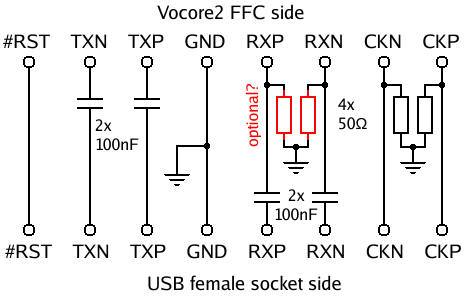
 I've just shorted the pads, because I already have the caps on my interface adapter from the previous PCB version of the vocore2. You can always add more caps in series anyway (as we will see later).
  +-------+
+-+-------+-+
| G       G | <- mechanical/shielding
|  1 2 3 4  | <- original USB 2.0 pins (Vbus, D-, D+, GND)
| 9 8 7 6 5 | <- additional USB 3.0 pins (TX+, TX-, GND, RX+, RX-)
+-----------+

G - shielding ground
1 - unconnected (unpowered adapter)
2 - CKn (refclk-)
3 - CKp (refclk+)
4 - #RST
5 - TXp (TX+)
6 - TXn (TX-)
7 - ground
8 - RXp (RX+)
9 - RXn (RX-)
 The caps are probably 40 years old, but the PCIe signal still goes through . The capacitance deviation is about up to 125 nF on a 100 nF part. The RX caps were added later.
For the overall design, the wires in one pair must be as much length matched as possible. The lengths between TX, RX and CLK pairs does not depend on each other. The polarity of the clock pair can be switched obviously, the device will get a different phase anyway. Some PCIe controllers allow the switch of TX/RX pair signals (not MT7628).
The caps are probably 40 years old, but the PCIe signal still goes through . The capacitance deviation is about up to 125 nF on a 100 nF part. The RX caps were added later.
For the overall design, the wires in one pair must be as much length matched as possible. The lengths between TX, RX and CLK pairs does not depend on each other. The polarity of the clock pair can be switched obviously, the device will get a different phase anyway. Some PCIe controllers allow the switch of TX/RX pair signals (not MT7628).
 It seems the board can have two power supply configuration. Both generates 3.3 V for the respective slots from the global 5 V input (molexes or PCIe 8pin connected in parallel). The first configuration uses a linear regulator and the second seems to use DC-DC converter. The board I've bought have the variant with linear regulator. A PCIe card can consume up to 3 A from 3.3 V rail, so the regulator AP1084 seems to be fine to that job. The 12 V lines for the PCIe slots are connected straight through, so 75W per slot is fine too.
The board uses an ASMedia ASM1184e chip. Sadly there is no datasheet, only a webpage.
The chip supports up to PCIe gen2 speeds.
The "USB" connector pinout is described below, bottom side (THT solder pins) view, USB connector is from the top. You can compare the signals with wikipedia.
It seems the board can have two power supply configuration. Both generates 3.3 V for the respective slots from the global 5 V input (molexes or PCIe 8pin connected in parallel). The first configuration uses a linear regulator and the second seems to use DC-DC converter. The board I've bought have the variant with linear regulator. A PCIe card can consume up to 3 A from 3.3 V rail, so the regulator AP1084 seems to be fine to that job. The 12 V lines for the PCIe slots are connected straight through, so 75W per slot is fine too.
The board uses an ASMedia ASM1184e chip. Sadly there is no datasheet, only a webpage.
The chip supports up to PCIe gen2 speeds.
The "USB" connector pinout is described below, bottom side (THT solder pins) view, USB connector is from the top. You can compare the signals with wikipedia.
  +-------+
+-+-------+-+
| G       G | <- mechanical/shielding
|  1 2 3 4  | <- original USB 2.0 pins (Vbus, D-, D+, GND)
| 9 8 7 6 5 | <- additional USB 3.0 pins (TX+, TX-, GND, RX+, RX-)
+-----------+

G - connector shield ground
1 - 3.3 V
2 - refclk-, pin A14 of the host PCIe slot
3 - refclk+, pin A13
4 - PERST#, system reset, pin A11
5 - TX+, board data output, connected to the host PCIe slot pin A16
6 - TX-, board data output, connected to the host PCIe slot pin A17
7 - WAKE#, link reactivation, pin B11
8 - RX+, board data input, connected from the host PCIe slot pin B14
9 - RX-, board data input, connected from the host PCIe slot pin B15
 The expander comes with a PCIe riser "card" pluggable into your PCIe slot on motherboard. I would not use different risers from different expanders, the pin mapping of the USB cable is not standardized and some others (as we will see) can route 12 V power supply, which would burn the DC-DC and switch altogether.
. I was thinking about buying a PCI-PCIe adapter anyway. There is only few boards available. I've opted for the one with a USB cable which looks mechanically robust. You can find them under the keyword "PCI-E Express X1 to Dual PCI Riser Extend Adapter Card".
The board is based on Pericom PI7C9X111SL PCI Express-to-PCI Reversible Bridge. The "reversible" means it can act as the bridge from a PCI-e computer to a PCI card or it can act as the bridge from a PCI computer to a PCI-e card ... you get the idea. It could be entirely possible (and hilarious) to rewire the bridge and plug a PCIe card into my old 486 board .
The expander comes with a PCIe riser "card" pluggable into your PCIe slot on motherboard. I would not use different risers from different expanders, the pin mapping of the USB cable is not standardized and some others (as we will see) can route 12 V power supply, which would burn the DC-DC and switch altogether.
. I was thinking about buying a PCI-PCIe adapter anyway. There is only few boards available. I've opted for the one with a USB cable which looks mechanically robust. You can find them under the keyword "PCI-E Express X1 to Dual PCI Riser Extend Adapter Card".
The board is based on Pericom PI7C9X111SL PCI Express-to-PCI Reversible Bridge. The "reversible" means it can act as the bridge from a PCI-e computer to a PCI card or it can act as the bridge from a PCI computer to a PCI-e card ... you get the idea. It could be entirely possible (and hilarious) to rewire the bridge and plug a PCIe card into my old 486 board .
 Unlike previous expander, this one has a lot of design problems. Let's start with board power. Like the previous expander this one can be powered from "USB" connector too, but unlike the previous, this one is using 12 V power from its riser card. If you use this expander's riser card for the first expander you will most likely blow it!
Thankfully you can desolder a serial schottky diode near the USB connector and make an unpowered expander.
Unlike previous expander, this one has a lot of design problems. Let's start with board power. Like the previous expander this one can be powered from "USB" connector too, but unlike the previous, this one is using 12 V power from its riser card. If you use this expander's riser card for the first expander you will most likely blow it!
Thankfully you can desolder a serial schottky diode near the USB connector and make an unpowered expander.
 You will then have to use an SATA power connector for powering the cards. That's the problem number two.
I don't know what was the designer thinking, but the version with a vertical SATA power connector is really dumb solution. If you plug a cable in you will block yourself from using long PCI cards (the length of the PCB must end with the last PCI pins). Even if you buy an "L" shaped SATA cable it will block the longer cards and I'm not speaking about 64bit PCI-X card (additional row of pins). There is still a way to fix this by populating DC jack (two possible positions, one can be blocked with schottky). At least the vertical SATA power connector doesn't block PCI-X card when unconnected. To use a DC jacks you will need to buy one or two 5 mm DC jack sockets and unscrew two metal rails around the board, the pads are under them.
Yet another problem is the power. The whole board with two PCI slot and any cards in it will be powered by a single 12 V source. Other PCI power rails (5 V, 3.3 V) are generated by a DC-DC and a linear regulator. It seems the DC-DC is not powerful enough to deliver the power to a PCI card which fits the PCI specifications. Doing that will overheat the DC-DC chip (it will start to periodically cycle the power ). The next figure is simplified power sources of the board.
You will then have to use an SATA power connector for powering the cards. That's the problem number two.
I don't know what was the designer thinking, but the version with a vertical SATA power connector is really dumb solution. If you plug a cable in you will block yourself from using long PCI cards (the length of the PCB must end with the last PCI pins). Even if you buy an "L" shaped SATA cable it will block the longer cards and I'm not speaking about 64bit PCI-X card (additional row of pins). There is still a way to fix this by populating DC jack (two possible positions, one can be blocked with schottky). At least the vertical SATA power connector doesn't block PCI-X card when unconnected. To use a DC jacks you will need to buy one or two 5 mm DC jack sockets and unscrew two metal rails around the board, the pads are under them.
Yet another problem is the power. The whole board with two PCI slot and any cards in it will be powered by a single 12 V source. Other PCI power rails (5 V, 3.3 V) are generated by a DC-DC and a linear regulator. It seems the DC-DC is not powerful enough to deliver the power to a PCI card which fits the PCI specifications. Doing that will overheat the DC-DC chip (it will start to periodically cycle the power ). The next figure is simplified power sources of the board.
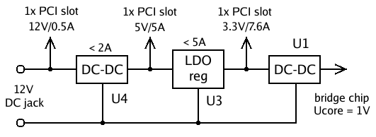 You should be able to put two PCI cards, where a single one can eat up to 25 W. Imagine a supply of 50 W (+ losses from board) pulling through a cheap USB 3.0 cable (or even FFC in the case of the vocore ). Funny thing is, there are all three rails in the SATA power connector, but the board is using only 12 V (in the times of PCI, the 12 V current limit was just a few hundreds of miliamps). For my power hungry PCI cards I'm gonna need to add an external supply on the PCI riser cable. Alternatively the chips U3 and U4 could be desoldered.
BTW only 2 of 5 VIO pins of the PCI slot are connected to the 5 V rail.
However the most funniest bug is the last one. I found from my hacking it has DC blocking series capacitors (C8, C9) on the RX lane and none on the TX lane (exactly in the opposite way it should had to be). The propagated DC is serious enough so it will not work with vocore2. However it worked with Intel ICH7 on thinkpad, it has probably a better signal drivers, but the connection was weak. Remember I've said it is better to put caps on both lanes of the vocore adapter? That's why! Ideally they would be just shorted out, but the series connected capacitors are still capacitor (that's why is better to put a bigger caps into the vocore adapter).
BTW datasheet for the chip claims there must be AC coupling caps on the refclock PCIe lane (C4, C5 on the board).
Other than that there is not much more thing about the bridge to be said. Just maybe there is a boundary scan of the chip, some register for fine tuning of the RX termination. The bridge was really useful for debugging of the interrupts of the MT7628 PCIe kernel driver (just shorting the pins) and to fix the PCIe driver in general (PCI sound card for busmastering and IO port correctness).
The pinout of the USB connector on the dual PCI board looks like this:
You should be able to put two PCI cards, where a single one can eat up to 25 W. Imagine a supply of 50 W (+ losses from board) pulling through a cheap USB 3.0 cable (or even FFC in the case of the vocore ). Funny thing is, there are all three rails in the SATA power connector, but the board is using only 12 V (in the times of PCI, the 12 V current limit was just a few hundreds of miliamps). For my power hungry PCI cards I'm gonna need to add an external supply on the PCI riser cable. Alternatively the chips U3 and U4 could be desoldered.
BTW only 2 of 5 VIO pins of the PCI slot are connected to the 5 V rail.
However the most funniest bug is the last one. I found from my hacking it has DC blocking series capacitors (C8, C9) on the RX lane and none on the TX lane (exactly in the opposite way it should had to be). The propagated DC is serious enough so it will not work with vocore2. However it worked with Intel ICH7 on thinkpad, it has probably a better signal drivers, but the connection was weak. Remember I've said it is better to put caps on both lanes of the vocore adapter? That's why! Ideally they would be just shorted out, but the series connected capacitors are still capacitor (that's why is better to put a bigger caps into the vocore adapter).
BTW datasheet for the chip claims there must be AC coupling caps on the refclock PCIe lane (C4, C5 on the board).
Other than that there is not much more thing about the bridge to be said. Just maybe there is a boundary scan of the chip, some register for fine tuning of the RX termination. The bridge was really useful for debugging of the interrupts of the MT7628 PCIe kernel driver (just shorting the pins) and to fix the PCIe driver in general (PCI sound card for busmastering and IO port correctness).
The pinout of the USB connector on the dual PCI board looks like this:
  +-------+
+-+-------+-+
| G       G | <- mechanical/shielding
|  1 2 3 4  | <- original USB 2.0 pins (Vbus, D-, D+, GND)
| 9 8 7 6 5 | <- additional USB 3.0 pins (TX+, TX-, GND, RX+, RX-)
+-----------+

G - connector shield ground
1 - 12 V, the PCIe "card" for this board will kill other extenders!!!
2 - refclk-, pin A14 of the host PCIe slot
3 - refclk+, pin A13
4 - PERST#, system reset, pin A11
5 - TX+, board data output, connected to the host PCIe slot pin A16
6 - TX-, board data output, connected to the host PCIe slot pin A17
7 - ground, the board will short the slot's WAKE# if you use different card (maybe it is opendrain driver)
8 - RX+, board data input, connected from the host PCIe slot pin B14
9 - RX-, board data input, connected from the host PCIe slot pin B15
  +-------+
+-+-------+-+
| G       G | <- mechanical/shielding
|  1 2 3 4  | <- original USB 2.0 pins (Vbus, D-, D+, GND)
| 9 8 7 6 5 | <- additional USB 3.0 pins (TX+, TX-, GND, RX+, RX-)
+-----------+

G - connector shield ground
1 - WAKE#, link reactivation, pin B11, different pin than on 4x port board! (3.3 V)
2 - refclk+, pin A13 (clock pins have a switched polarity!, doesn't matter for the function)
3 - refclk-, pin A14
4 - PERST#, system reset, pin A11
5 - TX+, board data output, connected to the host PCIe slot pin A16
6 - TX-, board data output, connected to the host PCIe slot pin A17
7 - ground, different function than on 4x port board! (WAKE#)
8 - RX+, board data input, connected from the host PCIe slot pin B14
9 - RX-, board data input, connected from the host PCIe slot pin B15
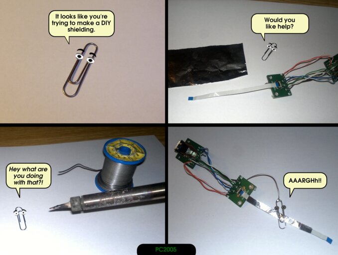
 Obviously it didn't work , but it taught me what the meaning of length matching means. I've tried to make the wires (from disassembled ignition coil) as twisted pairs (IMO bad idea for PCIe) and even with some shielding around.
 You would be surprised but the one use (out of many re-plugs) of the card the notebook actually detected the PCIe device (and lost it immediately afterwards). Next the third version was resoldered (again 1 mm pitch on the plastic) with some telephone wires (thin enough to fit inside), and the adapter is working!
 .
.
 Later I've desoldered the connector and drilled the hole completely.
I'm advising you to buy an adapter which has just a one-to-one pin mapping. Something like this one (may not be actual anymore).
It has worse pair length matching, but I guess it is fine for 100 MHz clocks and you can always fix the lengths by shortening the other wires around.
Later I've desoldered the connector and drilled the hole completely.
I'm advising you to buy an adapter which has just a one-to-one pin mapping. Something like this one (may not be actual anymore).
It has worse pair length matching, but I guess it is fine for 100 MHz clocks and you can always fix the lengths by shortening the other wires around.
mt7620_pci_probe() function. If the signal is unstable at that moment the PCIe functionality will be lost until the next boot. It is really difficult to debug the adapter under these conditions. Thankfully there is a easy solution. No one says you cannot use /dev/mem (well unless you are using a secureboot PC setup ). When the kernel driver is disabled, you can meddle with PCIe controller without any sanctions. For example you can control the sampling of the soundcard from the shell alone with devmem (devmem2/memtool/...) application. It can be used to optimize the PCIe adapter. I've managed to found a few undocumented registers for this reason. There is a link quality register at 0x101490c4 address (undocumented region 0x9000 of the controller). The various values from an undocumented register 0x101490c4 measured during testing are logged below.
The usual values when the PCIe link is disconnected:
0x00000073
0x00000072
0x00000062  #when no adapter board is connected (no resistors)
0x00000072
0x00004c73
0x00005077
0x00004077
0x00004c73
0x00004477
0x00004877
0x00005c77
0x00003c67
0x00007c77
0x00000877
0x00007c77
0x00000477
0x00000477
0x00000477
0x00000477
15:8 seems to correlate with the connection quality. When I've pressed the broken FFC connector the value got higher. I would say it is an RX quality indicator. The bits 7:0 seems to be almost always 0x67, sometimes 0x66. It could be MSB from the RX quality or it could be some feedback about the quality of transmitted data.
When I've held the FFC cable in both hands the value was the highest. The FFC shielding could be probably improved then.
 So now the grounding of the board is connected to the shielding of the FFC cable, it is connected to the shielding of the DIP to USB3 connector board, and to the AT PSU too (there is a ground for the external USB 2.0 device, connected to the PSU as well). The grounding over micro USB cable to the main computer is somewhat weak (some cables doesn't even have the connected connector shieldings together, some has really big resistance between two endings, we will see that in the USB 2.0 host section ... ).
/dev/mem access, so you don't need the JTAG even for busmaster transactions.
 ##### The CPU freq = 575 MHZ ####
 estimate memory size =256 Mbytes
RESET MT7628 PHY!!!!!!
Please choose the operation:
   0: Load system code then write to Flash via Serial.
   1: Load system code to SDRAM via TFTP.
   2: Load system code then write to Flash via TFTP.
   3: Boot system code via Flash (default).
   4: Enter boot command line interface.
   5: Load system code then write to Flash via USB Storage.
   7: Load Boot Loader code then write to Flash via Serial.
   9: Load Boot Loader code then write to Flash via TFTP.

You choosed 1
1 enables you to load a uimage kernel over tftp into RAM and run it. The waiting interval is rather short, so the ideal thing is just to hold the 1 key and power on the board. I'm using minicom which cannot open the tty device if it is not present, but once it is opened it will stay that even is the device disappear so you need to power on the board, start the minicom and then restart the power. Sometimes the USB device enumeration is too slow the minicom takes too much time and misses the waiting interval and must be restarted. You could flash your devel kernel into the whole SPI flash (these are usually big, so you would need to delete openwrt), but the frequent recompilations would wear out the flash soon. Theoretically the best thing would be to set the different default boot option in uboot configuration, but a study of uboot source code shows it is not possible. The string "Boot system code via Flash (default)." in OperationSelect() is a predefined string altogether with the predefined code path for the default option. To change that (should be easy) you need to patch the code and reflash the uboot. I'm using the manual way with the reset (because I would be too lazy to reflash the failed uboot update ), the board needs to be frequently power cycled anyway.
I've set the following uboot variables (printenv):
ipaddr=10.0.0.199
serverip=10.0.0.1
autostart=no
bootfile=test5.bin
 After the change it worked, although very slow (I have only class 10 cards). Problem was the constant need to unplug the card, which meant to unplug the usb cable too. This seemed to worn out the micro USB connector of the Vocore2 and the connection stability went down.
Why not use the NFS rootfs then. You need to compile the kernel with CONFIG_ROOT_NFS option to make that possible. If you are at it, you can enable the option CONFIG_NFS_SWAP as well .
This leads to the question what distribution will you use. The ideal for the testing is just the busybox alone, but you can have almost anything with NFS server space, so I've decided to install Debian.
. There isn't many to say about the installation in the Qemu, I think I wasn't able to make a virtual card running, so the distribution wasn't updated, otherwise than that it was pretty quick.
Oh yeah and disable systemd it eats too much memory for an embedded and we have only 128 MiB and you may need to kill some apps just from the console later.
After the installation all you need to do is to copy the files from Qemu virtual disk to NFS directory, fix some standard
After the change it worked, although very slow (I have only class 10 cards). Problem was the constant need to unplug the card, which meant to unplug the usb cable too. This seemed to worn out the micro USB connector of the Vocore2 and the connection stability went down.
Why not use the NFS rootfs then. You need to compile the kernel with CONFIG_ROOT_NFS option to make that possible. If you are at it, you can enable the option CONFIG_NFS_SWAP as well .
This leads to the question what distribution will you use. The ideal for the testing is just the busybox alone, but you can have almost anything with NFS server space, so I've decided to install Debian.
. There isn't many to say about the installation in the Qemu, I think I wasn't able to make a virtual card running, so the distribution wasn't updated, otherwise than that it was pretty quick.
Oh yeah and disable systemd it eats too much memory for an embedded and we have only 128 MiB and you may need to kill some apps just from the console later.
After the installation all you need to do is to copy the files from Qemu virtual disk to NFS directory, fix some standard /etc files (things like /etc/fstab and swap file use) and use your kernel compiled for Vocore2.
.
This is clearly inefficient, so the better solution can be made. The Vocore2 has a USB 2.0 controller, why not use that. So I've bought some really cheap USB 3.0 16 GB flash drive and copied the NFS directory onto that (from Qemu to NFS to flashdriver, heh try to do than with windows).
BTW OK there was a very short test with an old 4 GB compact flash card inside USB reader. It was faster than the rootfs over the ethernet, but slow anyway (and 4 GB is a small space). ... I almost skipped mentioning it. The read/write speeds was around 20 MBps/2.5 MBps.
CONFIG_USB_EHCI_HCD_PLATFORM and CONFIG_USB_OHCI_HCD_PLATFORM (and dependent CONFIG_USB_*_PCI) into the kernel if you want to boot from USB. The option CONFIG_PHY_RALINK_USB is required too. The drivers should be stable enough.
What is interesting is the MT7620 (sort of an older version of the board) supports USB device mode but the datasheet to MT7628 doesn't mention anything about that. The both of them is using the same phy driver, which is in the same region at the same address 0x10120000. So maybe the device controller could be enabled even it is not documented in MT7628 datasheet. I poked for a very short time around, but I didn't found anything significant (didn't try that much). The device/host switch USB0_HOST_MODE for MT7620 is located in the SYSCFG1 register and on the MT7628 the switch has the correct value 1 (host mode).
A worse problem arises with a USB flashdrive. As I've said before the micro USB cables are poor and there is a big voltage drop. Even with the USB flashdrive connected directly to the Vocore2 the current load on the micro USB was too big the voltage dropped to less than 4.6 V (I think even about 4.4 V one time. This is too low voltage for the flashdrive to run, so it will reset itself and sometimes altogether with Vocore2. The solution is easy, you can just make a straight through USB cable with a disconnected voltage line and apply an external voltage (an AT PSU in my case) for just the device side. The original Vocore2 (dock piece) is constructed in a way the 5 V line is directly connected from micro USB to USB 2.0 host connector. You could probably cut the voltage line from micro USB cable and supply the system from Vocore2 5 V pins (don't forget to check any newer PCB versions if they are compatible).
The USB 3.0 flashdrive with and external supply works great, but it is still little bit slow. The cheap flashdrives are really slow for writes. USB 2.0 practical limit is like 20-30 MByte/s (link speed is 480 Mbps, but there are protocol overheads and the wires are half duplex). The real reads/writes were around 24/18 MBps. Much better speeds than ethernet/CF card .
But we are not done. The 16 GB flashdrive is nice, but I felt there is still some reserve and exceptionally with random RW speeds on small blocks (swap). The space started to be small again too. I'm not gonna buy another slow but a bigger flashdrive (I did :-P), so I've bought an SSD drive (WD green 128 GB) as the price went really down last year (actually some are cheaper than an equivalently sized flashdrive, but much faster). As Vocore2 doesn't have SATA we need to get USB-SATA adapter (and it is still cheaper than some USB flashdrives).
And because we don't have any IO device, we can buy a hub and put an old keyboard and mouse into it (so don't forget enable the HID option for the kernel and another USB devices which you like to use - scanner maybe? ).
The drive will be more efficient with a small random IO too. The Debian runtime is very fast with this configuration, even with the low system memory.
The SSD drive seems to have the fastest RW speed. The read saturates the USB (2.0) at 30 MBps. But the fastest drive communications I've seen is when I put an SATA card into the PCIe:
01:00.0 SATA controller: ASMedia Technology Inc. ASM1062 Serial ATA Controller (rev 02) (prog-if 01 [AHCI 1.0])
cat /dev/sda | pv > /dev/null
    ~42 MBps
cat /dev/zero | pv > /tempfile.del
    ~27 MBps
[  313.318369] ata1.00: exception Emask 0x10 SAct 0x78001fff SErr 0x400000 action 0x6 frozen
[  313.340692] ata1.00: irq_stat 0x08000000, interface fatal error
[  313.356719] ata1: SError: { Handshk }
[  313.368731] ata1.00: failed command: WRITE FPDMA QUEUED
[  313.384649] ata1.00: cmd 61/b8:00:00:6b:e6/00:00:02:00:00/40 tag 0 ncq dma 94208 out
[  313.384649]          res 40/00:00:00:00:00/00:00:00:00:00/00 Emask 0x10 (ATA bus error)
[  313.430923] ata1.00: status: { DRDY }
[  313.442913] ata1.00: failed command: WRITE FPDMA QUEUED
[  313.461008] ata1.00: cmd 61/a8:08:b8:6b:e6/08:00:02:00:00/40 tag 1 ncq dma 1134592 ou
[  313.461008]          res 40/00:00:00:00:00/00:00:00:00:00/00 Emask 0x10 (ATA bus error)
[  313.507945] ata1.00: status: { DRDY }
 Meh...
SCSI controller with a tape drive?
Meh...
SCSI controller with a tape drive?
 Or even RAID SCSI?
 Well yeah the Adaptec controller worked, but having an NAS tape drive with 1.5 Mbps speed is boring even if it could make a wifi NAS. The testing tape got torn off anyway :-/ and the driver freezes at the second tape record. The RAID SCSI card seems to have lost the support in the kernel just a few years back and it isn't even a standard SCSI layer device and it doesn't support SCSI tapes (it should be able to switch itself into a pass-through mode).
An another computer, this time pentium III on a PCI card?
Well yeah the Adaptec controller worked, but having an NAS tape drive with 1.5 Mbps speed is boring even if it could make a wifi NAS. The testing tape got torn off anyway :-/ and the driver freezes at the second tape record. The RAID SCSI card seems to have lost the support in the kernel just a few years back and it isn't even a standard SCSI layer device and it doesn't support SCSI tapes (it should be able to switch itself into a pass-through mode).
An another computer, this time pentium III on a PCI card?
 Yeah why not, but I'm lazy to add 25 W power rails to PCIe-PCI bridge board (you can always somehow convince me, for example a 133 MHz SO-DIMM SDRAM 256+ MiB would be nice to have to use it for the tests ).
Soooo... Let's play with some GPUs!!
Yeah why not, but I'm lazy to add 25 W power rails to PCIe-PCI bridge board (you can always somehow convince me, for example a 133 MHz SO-DIMM SDRAM 256+ MiB would be nice to have to use it for the tests ).
Soooo... Let's play with some GPUs!!
 You know the main question of any new device: Will it run Doom?
Let's try to make that happen.
You know the main question of any new device: Will it run Doom?
Let's try to make that happen.
radeon_bo_create() function, especially at the place of setting the flags:
    bo->flags &= ~(RADEON_GEM_GTT_WC | RADEON_GEM_GTT_UC);
#else
    /* For architectures that don't support WC memory,
    * mask out the WC flag from the BO
    */
    if (!drm_arch_can_wc_memory())
        bo->flags &= ~RADEON_GEM_GTT_WC;
#endif

    radeon_ttm_placement_from_domain(bo, domain);
RADEON_GEM_GTT_WC, but it may not set uncached flag RADEON_GEM_GTT_UC. This will probably cause problem with evaluation in radeon_ttm_placement_from_domain().
} else {
    rbo->placements[c].fpfn = 0;
    rbo->placements[c++].flags = TTM_PL_FLAG_CACHED |
                    TTM_PL_FLAG_TT;
}
TTM_PL_FLAG_CACHED flag as none previous condition check have succeeded. The rest of the if-else codepaths seems to have the same problem, so change them too. The first-quick hack was to the next code into radeon_bo_create() function after the arch preprocessor code.
    if (!drm_arch_can_wc_memory())
        bo->flags &= ~RADEON_GEM_GTT_WC;
#endif

#if defined(CONFIG_SOC_MT7620)
/* vocore */
    bo->flags |= RADEON_GEM_GTT_UC;
#endif

radeon_ttm_placement_from_domain(bo, domain);
ttm_io_prot() to be always "noncached". If you manage to make the more universal solution, feel free to write it in the comments (or you can send the patch to the upstream ).
BTW I was playing with the macros for kmap functions too.
I was testing if the x86 version have some speed impact on the MIPS. The results are rather inconclusive (but it seems both variants works at least). There might be a little higher FPS for the vmap version but only about 1 percent or something like that.
Apart of a ton of asserts. There is one really important function which is missing on MIPS. It is a nonexistent "q" version (64bit) of the memory RW operations. The radeon driver is using these accesses for GART set page and the 32bit MIPS doesn't have the general architectonical support for 64bit atomical RW. As we can see below (backslashes redacted) the source is in io.h, it took a while to find that, Linux Cross Reference doesn't evaluate these crazy macros.
if (sizeof(type) != sizeof(u64) || sizeof(u64) == sizeof(long))
    *__mem = __val;
else if (cpu_has_64bits) {
    unsigned long __flags;
    type __tmp;

    if (irq)
        local_irq_save(__flags);
    __asm__ __volatile__(
        ".set   push"       "\t\t# __writeq""\n\t"
        ".set   arch=r4000"         "\n\t"
        "dsll32 %L0, %L0, 0"            "\n\t"
        "dsrl32 %L0, %L0, 0"            "\n\t"
        "dsll32 %M0, %M0, 0"            "\n\t"
        "or %L0, %L0, %M0"          "\n\t"
        "sd %L0, %2"            "\n\t"
        ".set   pop"                "\n"
        : "=r" (__tmp)
        : "0" (__val), "m" (*__mem));
    if (irq)
        local_irq_restore(__flags);
} else
    BUG();
BUG() because on 32bit arch, the 64bit access will not be atomic (compiled as two load/stores). Theoretically some interrupt could intercept the code just in between of the two instructions and the code in the interrupt handler could access the same memory address too. It doesn't have to be an interrupt it can be just another core. The solution would be to put a spinlock at every writeq/readq call in the radeon driver, put a spinlock inside this macro or you can just risk it, copy the 64bit generic branch and replace the BUG() call with something like this:
} else {
    unsigned long __flags;
    if (irq)
        local_irq_save(__flags);
    *__mem = __val;
    if (irq)
        local_irq_restore(__flags);
}
make nconfig (and you can see it with F8 + "name" key). After that the radeon driver should be ready.
Notice: If you compile the GPU driver into the kernel completely it may fail even if you install the firmware. This is because the firmware file is located on the drive which isn't initialized when the GPU driver requests it. You can put the firmware into the initrd image (but these are ugly on MIPS system) or you can reload the driver later after it booted by rebinding it to the PCI device:
echo "0000:01:00.0" > /sys/module/<driver>/drivers/pci\:<driver>/bind


 For the scope of this blog, let's assume you already have a second monitor .
). The DDR2 bus (only x16, and the chip is slow) is so narrow, that Duron/K7S5A board was actually faster (SDR 64bit @133 MHz, dual channel). The internal bus of the system is probably slow too. After some playing with xorg-radeon driver options I've managed to run glx-gears with VSYNC disabled and with 800x600 fullscreen at 78 fps, which is just above the 60 Hz refresh rate of the panel. Most likely the bottleneck is the bandwidth of GPU commands, don't forget everything is uncached.
of on some slow flashdrive, or on SSD, but still it will swap). You need of course to disable all unnecessary applications. Who needs syslog and dhcp client anyway, disable ALSA, although some games will crash without alsa, load only dummy driver. Effectively only an SSH server, Xorg server and the application will run at the most times. You may even disable ssh server if you will control the system from a serial console (over the micro USB cable).
... and this was around the time my first vocore2 board burned out, because of bad groundings around FFC cable for PCIe.
I've decided to order the new batch around May 2019, which some catch. I've asked the developer if the 256 MiB DDR2 chip is possible. It should be, according to the MT7628 datasheet and some offers for 256 MiB upgrade at aliexpress (MT7628 can used as a really cheap wifi/fast-eth router). I've had to ask about MT7628AN chip version anyway (the current MT7628NN version doesn't have a PCIe controller). After some problems about fitting a double sized chip on the PCB the developer managed to found a compatible RAM chip. BTW the original 128 MiB model uses a samsung DDR2, which is a thinner chip than samsung's competitors offers (a little bit of a mechanical vendor lock-in ). It could be probably fine (0.5 mm overlap is compatible with rasping anyway...), but some near filtration capacitors were removed.
I've had to buy a new pinheader for the connection to the original dock (the board with micro USB, ethernet and a sound chip). I wasn't able to found the original 1.27 mm pinheaders anywhere. It seems the original pinheaders (2 mm wide, 2 mm tall) doesn't exist on this planet! I've managed to desolder the old ones from the original Vocore2 batch, but they break so easily and then can get accidentally filled with tin during the soldering (the pin itself is in a sub 1 mm sizes ). One board from the new batch got partially the rests of the old pinheaders. But for the second Vocore2 (the one with 256 MiB chip) I've waited for the compatible pinheaders. I was worried if the compatible pinheaders will fit as they are neighbors with the RAM chip, but it seems they are fine (the new floorplan for the 256 MiB option would be nice though). The new compatible pinheader had the same width, but it is taller (4 mm vs 2 mm). It is compatible with the dock and most importantly it exists on this planet .
The problem is the old radeon x1300 LE GPU had burned too. As a replacement I've bought the newer card, ATI radeon HD4550. Well why buy one if you can have two twice the price ... so I've bought two of them . At least I'm safe if there is another floating ground event.
For the scope of this blog, let's assume you already have a second monitor .
). The DDR2 bus (only x16, and the chip is slow) is so narrow, that Duron/K7S5A board was actually faster (SDR 64bit @133 MHz, dual channel). The internal bus of the system is probably slow too. After some playing with xorg-radeon driver options I've managed to run glx-gears with VSYNC disabled and with 800x600 fullscreen at 78 fps, which is just above the 60 Hz refresh rate of the panel. Most likely the bottleneck is the bandwidth of GPU commands, don't forget everything is uncached.
of on some slow flashdrive, or on SSD, but still it will swap). You need of course to disable all unnecessary applications. Who needs syslog and dhcp client anyway, disable ALSA, although some games will crash without alsa, load only dummy driver. Effectively only an SSH server, Xorg server and the application will run at the most times. You may even disable ssh server if you will control the system from a serial console (over the micro USB cable).
... and this was around the time my first vocore2 board burned out, because of bad groundings around FFC cable for PCIe.
I've decided to order the new batch around May 2019, which some catch. I've asked the developer if the 256 MiB DDR2 chip is possible. It should be, according to the MT7628 datasheet and some offers for 256 MiB upgrade at aliexpress (MT7628 can used as a really cheap wifi/fast-eth router). I've had to ask about MT7628AN chip version anyway (the current MT7628NN version doesn't have a PCIe controller). After some problems about fitting a double sized chip on the PCB the developer managed to found a compatible RAM chip. BTW the original 128 MiB model uses a samsung DDR2, which is a thinner chip than samsung's competitors offers (a little bit of a mechanical vendor lock-in ). It could be probably fine (0.5 mm overlap is compatible with rasping anyway...), but some near filtration capacitors were removed.
I've had to buy a new pinheader for the connection to the original dock (the board with micro USB, ethernet and a sound chip). I wasn't able to found the original 1.27 mm pinheaders anywhere. It seems the original pinheaders (2 mm wide, 2 mm tall) doesn't exist on this planet! I've managed to desolder the old ones from the original Vocore2 batch, but they break so easily and then can get accidentally filled with tin during the soldering (the pin itself is in a sub 1 mm sizes ). One board from the new batch got partially the rests of the old pinheaders. But for the second Vocore2 (the one with 256 MiB chip) I've waited for the compatible pinheaders. I was worried if the compatible pinheaders will fit as they are neighbors with the RAM chip, but it seems they are fine (the new floorplan for the 256 MiB option would be nice though). The new compatible pinheader had the same width, but it is taller (4 mm vs 2 mm). It is compatible with the dock and most importantly it exists on this planet .
The problem is the old radeon x1300 LE GPU had burned too. As a replacement I've bought the newer card, ATI radeon HD4550. Well why buy one if you can have two twice the price ... so I've bought two of them . At least I'm safe if there is another floating ground event.
 The best thing about opensource radeon driver is that you don't need to change anything. The system should work right after you swap the old architecture card for the newer one. You need only to install the correct firmware from nonfree repo again (but I think they are all in one debian package). After the new vocore2 board was ready, adapter was updated with more shielding and I've updated the debian, I've plug the new radeon HD4550 card into it and ... it didn't work! (what a surprise ).
These small embedded boards usually have only a few megabytes of PCIe mappable memory. The PCIe region space is a memory, where the individual PCI BARs are mapped, so any IOMEM access from the CPU will be sent to the correct PCI device. There is a granularity rule, that a region of a size must be aligned to the same size too (for example a 2 MiB region must begin at the address divisible by 2 MiB without a remainder). The rule is for the simplification of the address decoders (less transistors - faster decoding).
The problem is the GPU cards usually requires pretty big regions (framebuffer, command rings, buffers etc...). The MT7628 uses up to 256 MiB of its address range (address
The best thing about opensource radeon driver is that you don't need to change anything. The system should work right after you swap the old architecture card for the newer one. You need only to install the correct firmware from nonfree repo again (but I think they are all in one debian package). After the new vocore2 board was ready, adapter was updated with more shielding and I've updated the debian, I've plug the new radeon HD4550 card into it and ... it didn't work! (what a surprise ).
These small embedded boards usually have only a few megabytes of PCIe mappable memory. The PCIe region space is a memory, where the individual PCI BARs are mapped, so any IOMEM access from the CPU will be sent to the correct PCI device. There is a granularity rule, that a region of a size must be aligned to the same size too (for example a 2 MiB region must begin at the address divisible by 2 MiB without a remainder). The rule is for the simplification of the address decoders (less transistors - faster decoding).
The problem is the GPU cards usually requires pretty big regions (framebuffer, command rings, buffers etc...). The MT7628 uses up to 256 MiB of its address range (address 0x2xxxxxxx) (BTW this is dumb memory map, there is an empty space at 0x3xxxxxxx, which could be used for 512 MiB region!) and the first radeon (x1300 LE) had 64 MiB BAR (it had only 64 MiB of RAM). Problem is the newer radeon has more memory and it uses one 256 MiB BAR and even some additional (~1 MiB) BAR (maybe for legacy VGA, not sure). It needs a ROM BAR too, which eats another memory from the MT7628 address space (you can force area in system memory for ROM though). It is obvious the BAR of the radeon doesn't fit into the Vocore2 address space. Even though the vocore2 PCIe space is really generous. Some other chips have much smaller space for PCIe, even the highend embedded boards like rockpro64 have only 64 MiB for the PCIe devices. The MT7628 isn't supposed to support GPU card, usually the PCIe is used for 802.11ac wifi card, which needs only something like 4 kiB of space. The bus master access can be done into the whole RAM, without any BAR, you need only to set its internal "DMA" registers, hence 4 kiB BAR. It is mainly the GPU card, which needs to have big regions for the communications. The radeon cards have - I think - some indirect modes, where the GPU itself can download any buffer by its internal DMA, but I think the kernel driver doesn't support indirect mode only.
I was upset by this as it effectively meant the card (two of them :-P ) won't ever work in vocore2. However I've got a hope when I've found some information from AMD official datasheets. Yeah there is an exhaustive documentation for the old R500 architecture. There is a documentation of central control unit, registers and even bootstrap settings (hah take that nvidia! :-P ). What is interesting is that some bootstrapping can be done from the SPI flash chip which holds video BIOS and one of these bootstrapped values is the BAR size!
This makes sense as the core of the GPU will be the same, but you can have multiple RAM configurations and using a bigger BAR than your GPU RAM would be a wasting. Now where to found the correct settings for HD4550? This is where I don't exactly remember how I've found that. It was series of lucky accidents. I was debugging the PCIe controller driver in the kernel which meant constant reboots, where sometimes the card was reset, sometimes wasn't, sometimes the reset signal and duration didn't have a correct quality. I was trying to dump the SPI flash by an SOIC clip programmer during that time too. I was comparing the images from multiple models and I was writing here and there in configuration registers. I don't remember and I have only a faint memory at the one random time after the reboot the card reported a smaller BAR than its default state. It is rather funny, because when I did another round of searching I've found I've found the RV710 (the core of HD4550) datasheet AMD_RV710_ds_nda_1.01b.pdf with its address. It seems its original webpage is down (located from this forum).
But that doesn't matter the PDF can be found at different places on the internet anyways. It seems the datasheet is not available at the AMD documentation page, which is rather sad, the architecture is 11 years old now so it doesn't matter to upload all documentation. It could help people who maintains drivers for these old cards.
The address of the ROM bootstrap can be easily regenerated from multiple vBIOSes. Obviously the SPI controller can support multiple chip sizes most likely the first page of the SPI standard will be used for the bootstrapping. It cannot be inside copyright strings nor the ROM code. This will usually returns only few bits of variability which you can bruteforce. There are other datasheets for the other radeon cores to take the inspiration for bitfields and some if the GPU if soldered in something like a notebook, there can be bootstrap GPIOs too. Or... you can use my values :-P:
| ROM offset | BAR size |
|---|---|
| 0x78, bits 9:7 | MEM_AP_SIZE |
| 000 | 128 MiB |
| 001 | 256 MiB |
| 010 | 64 MiB |
| other | reserved |
VGA_DIS (0x80), bit 0x27 if you don't want to use the ugly legacy VGA capability.
After that I think the card worked (I won't say flawlessly ... ). The speed of the system with HD4550 is again limited mostly by the slow memory access on MT7628 but now we have the system with 256 MiB RAM. We can do more funny things.
BTW with 64 MiB BAR size we can put two HD4550 cards simultaneously into the PCIe port multiplier and there still will be some space left. I didn't try it, but it it most likely the opensource driver would work in that configuration too. I wonder if the team who developed HD4550 hardware thought about that configuration .
Below are some photos of the applications, which I've run an Vocore2. The photos were shot with lowend phone camera .
You will notice a distortion of the LCD screen. The distortion is caused by very long wires for color parallel TTL signals leading to the realtek controller. There is a lot of crosstalks as the individual color bits nor the clock wires are not shielded. A hacked timing specs of the firmware is not helping either. The effect is more visible when high frequency of pixel brightness is displayed.
 LibreOffice Calc can run with 128 MiB version too, but really slowly. I was able to type the data and generate the graph even with distorted screen.
 We can use What-You-See-Is-What-You-Get editor, thankfully you would not get the distortion of the screen :-P. You can see unshielded LCD wire nest on the right of the second picture.
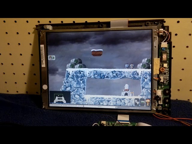
 An obvious game is openttd. It is not as fast as it could be, which is probably caused by holding many cells in the memory. It can run on 128 MiB configuration, but it brags about the low memory for textures.
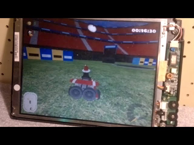
 The game TORCS is almost impossible to start and even with the best configuration it runs about 1 frame per minute.

 What about some Acid3 testing on Dillo?
 But the site of the blog works fine .
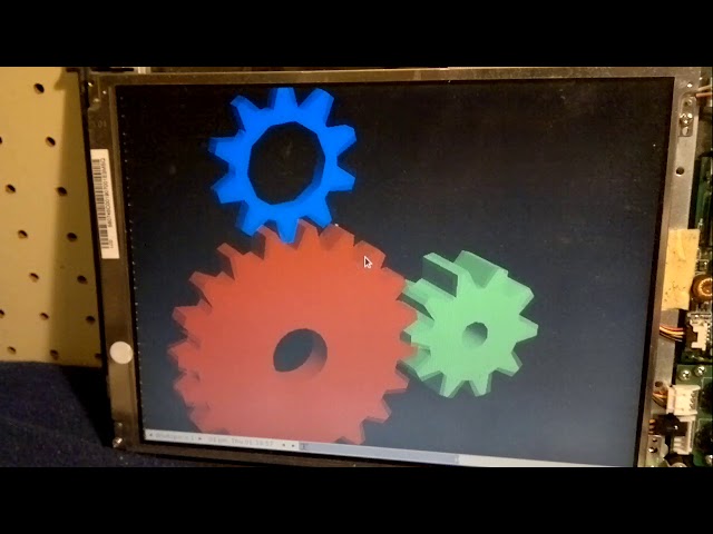
 Some screensavers run fine too.

 ... and even the Game of life, which I would guessed as memory intensive thing.
 Luckily I have some picture of doom clone with HD4550. Here it is.
 This game is almost impossible to run with 128 MiB of RAM. I was able to get only into the loading screen and even then it took minutes to display at least few icons and then it froze (a task which is done in few second on a normal computer). But with 256 MiB and with a long waiting times I've managed to "play" a little.
 https://www.youtube.com/watch?v=kJmI1ifVRiY:
 I've tried to do a "can it run the minecraft" test even on the first configuration of the 1st gen of Vocore2 with 128 MiB and with x1300 radeon. It was able to start into the menu, but the java JNI libraries were broken (libjwgl and jinput) so the controls were stuck on the menu screen. The minecraft version I've used was 1.7.3 beta without the launcher (I was to run it once on the old Duron/K7S5A board). The java version was probably openjdk 8 (Debian Buster fall 2018). There couldn't be any app other than java and Xorg on the system and even then the system swapped over 200 MB of data.
 I wasn't able to start the minecraft beta on the new configuration and Debian Sid at all. Probably java got updated. I wasn't trying that hard, because it would be slow anyway (even the minecraft in Qemu/MIPS was faster to start).
I've tried to run other game applications like:
) and it crashes there too (hah! vocore2 for PCIe cards testing works ). I've found after research the bug may be relative to some other bugreport, but nothing was done to the date I was testing the card. It might be a problem just with the firmware, which doesn't expects some commands, the kernel code seems fine (the card crashes just during the device test during the booting if enabled). I've reported the bugs #111634 and #111635.
Nevermind the normal openGL applications works, only slow. Isn't there more optimizations which can be done? Yes there actually is!
Debian MIPSel is compiled to be compatible with Malta board (roughly described). The problem is the simplest Malta board is only MIPS 4Kc, but the Vocore2 is MIPS 24KEc. I can illustrate this on pipeline length, 4K is only 5 stage, but 24K is 8 stage, so clearly it will be more complex. But the best thing is the "E" in "24KEc" of the Vocore2. It means the MIPS has DSP ASE, which is basically an SIMD unit. It can do vector operations, multiple and add operations, saturation, bitfield manipulation, etc. It doesn't support floats, which is another interesting thing about MIPS.
I wasn't able to start the minecraft beta on the new configuration and Debian Sid at all. Probably java got updated. I wasn't trying that hard, because it would be slow anyway (even the minecraft in Qemu/MIPS was faster to start).
I've tried to run other game applications like:
) and it crashes there too (hah! vocore2 for PCIe cards testing works ). I've found after research the bug may be relative to some other bugreport, but nothing was done to the date I was testing the card. It might be a problem just with the firmware, which doesn't expects some commands, the kernel code seems fine (the card crashes just during the device test during the booting if enabled). I've reported the bugs #111634 and #111635.
Nevermind the normal openGL applications works, only slow. Isn't there more optimizations which can be done? Yes there actually is!
Debian MIPSel is compiled to be compatible with Malta board (roughly described). The problem is the simplest Malta board is only MIPS 4Kc, but the Vocore2 is MIPS 24KEc. I can illustrate this on pipeline length, 4K is only 5 stage, but 24K is 8 stage, so clearly it will be more complex. But the best thing is the "E" in "24KEc" of the Vocore2. It means the MIPS has DSP ASE, which is basically an SIMD unit. It can do vector operations, multiple and add operations, saturation, bitfield manipulation, etc. It doesn't support floats, which is another interesting thing about MIPS.
-Ofast too .
CT_DEBUG_CT=yCT_DEBUG_CT_SAVE_STEPS=yCT_ARCH_TUNE="24kec"CT_ARCH_ARCH="24kec"CT_ARCH_FLOAT_SW=yCT_ARCH_FLOAT="soft"CT_TARGET_CFLAGS="-mdsp -msoft-float -Ofast"CT_TARGET_LDFLAGS="-flto"CT_CC_GCC_MULTILIB_LIST="march=24kec/mips32r2 msoft-float/mhard-float mdsp"-mdsp and -mno-dsp version.CT_DEMULTILIB=yCT_GLIBC_EXTRA_CFLAGS="-mdsp -Ofast -msoft-float"-Ox flag is most likely overridden by glibc configure mechanism, but the soft-float works. There seems to be a bug if you use -mno-dspr2 flag. The DSP r2 is a second version of the DSP and it adds additional instructions. The MT7628 supports only DSP r1. This GCC option will enable DSP r1 macros, but the compiler will try to use DSP r2 instruction and will fail. The bug was reported, but no reaction up to date.
It seems the DSP r1 instructions are emitted fine with just -mdsp option (there is a bug for a similar thing for ARM iwmmxt for pixman configuration, so I wanted to be sure ).
BTW Rockpro64 has only a small eMMC card to store the system and crosstool-ng would not fit (takes over 21 GB). I've decided to try to use a flashdrive for the storage. The nonFLT build on Rockpro64 took about 134 minutes, which is not that much slow, I've expected about 3 hours and it was over a slow flashdrive. The FLT build on x86 took 415 minutes, but the slower speed is caused by FTL optimizations. I will make a benchmark build on the same storage on both architectures but I guess the Rockpro64 is faster anyway.
The next step is to compile the buildroot "distribution". The buildroot is a bunch of scripts for automatized configuration and compilation of the whole distribution. It is something like openwrt, but much more configurable and it can be used for a bigger systems than openwrt's routers.
BR2_GCC_TARGET_ARCH is by default only mips32r2 which may or may not limit the full optimizations for the 24KEc, so the first change is forcing 24kec everywhere. Another problem is than multiple software doesn't support MIPSel soft float. For example luajit is even limited to the 32bit architecture of the building host. It seems it generates some tables and using 64bit compiler for 32bit target will destroy pointer addresses. Only supported host architecture is x86... This could be fixed easily by an installation of the 32bit ARM compiler into the debian. The current version of luajit is older than the latest beta (which is almost 2.5 years old too). In the distributed version the luajit fails on libffi compilation ARM, you need to use the oldest version. There is hardcoded x86 compiler flags in the scripts, these needs to be changed for ARM (only if you compile on ARM ofc).
Next change is the supported architecture for mesa. It seems the possibility of using mesa/radeon on MIPSel was not included (probably no machines for testing the configurations). That's easy to fix.
I was trying to make add the support for openJDK, but it is probably impossible. It needs to be compiled with only a very narrow range of the already existing java (usually previous version only). The buildroot download a special version somewhere from the net (had to be changed from x86 to ARM). Finally java doesn't support hotspot for MIPSel (only the slow Zero, without any assembler). The package failed to build anyway. There is even a second java VM in the buildroot, something called jamvm. It is heavily obsoleted project based on GNU classpath, which is obsoleted too. This practically abandoned project did build (after deleting one unicode character from the source files). Problem is some libraries don't exist anymore (dependency on GCJ). So much for a multiplatform language :-P.
The python2 requires to use --with-system-ffi or it will fail the compilation for the host (buildroot needs python2 for the host for some packages to configure).
I've explicitly added my CFLAGS to some speed critical libraries. The compiler is used as an external GCC from crosstool-ng (it is more modular solution).
The experimental cumulative patches are "package/python: use system ffi" and "vocore2 fixup2". Some patches are pending. The configuration file is here.
And to the compilation...
There wasn't any really fatal errors in the compilation, which couldn't be fixed in a few minutes (luckily buildroot doesn't need to rerun the complete build after a simple change). Maybe one fatal error was in few packages which heavily depends on hardfloat FPU state bits. These packages were either patched, or (usually) just disabled .
/etc files (swap, terminal, some services, ...) we can boot the new distribution and test the speed of glxgears. Don't forget to get firmware files from example the Debian setup.
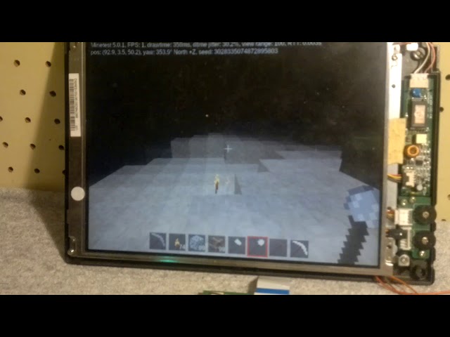
-mdsp, -Ofast) seems to run at almost playable speed. I was able to squeeze out about 4 fps out of it . With some more aggressive optimizations (I suspect a lot of projects will ignore the buildroot settings) it could be probably increased a little bit. This speedup is a little surprising for me, because the game must to check 3D cellular automaton grid many times per second, so one would say it will be memory intensive task. But it is probably really optimized to check only block where some events are going on because digging blocks lags a little bit and water spread lags a lot.
https://www.youtube.com/watch?v=JFlrvt1r9Z4:
 Now what happens when you play with the undocumented bits of
 0x10140000 PCIe controller register:
https://www.youtube.com/watch?v=dpgbJZEKfvs:

T_RFC from 0x1a to 0x8 in DDR_CFG0 register (0x10000340) and decreasing ADDITIVE_LATENCY to 0x1 in DDR_CFG3 register (0x1000034C). An example:
    devmem2 0x10000340 w 0x249902E5
    devmem2 0x1000034c w 0x44a
apt install blender
amdgpu_bo_placement_from_domain() for the setting the cache flag. Change all else branches from TTM_PL_FLAG_CACHED to TTM_PL_FLAG_UNCACHED and you'll fix this problem.
There were few forgotten calls for the code of a newer GPU core. It should be patched in the latest kernel versions.
There seems to be a long standing racing bug in the DDC access functions (open/close) starting there. I've found the problem some time ago on an independent update on my main computer. I've updated the amdgpu bugzilla about my findings, but no fixes up to this date were applied.
After applying these updates along with those for generic DRM subsystem, the card should start to work with Vocore2.
Nope again!
As we saw before, HD4550 didn't fit in the PCIe address space of MT7628. The RX460 is newer so it is obviously a worse situation. The card BARs are: 256 MiB, 2 MiB, 256 kiB, 128 kiB (for ROM) and one IOBAR. There is an audio function too, but it can be always disabled.
The polaris seems to support a dynamic change of the main BAR size by a Resizable BAR capability (PCIe standard). Unfortunately this capability starts only from 256 MiB to like 4 GiB. This was not a viable option. I was trying to research some info if there is again some bootstrap address in ROM as it was in HD4550 but I wasn't able to find any datasheets only some faint macro register names I think. BTW it is unfortunate there isn't any register reference material anywhere. The ROM bootstrap address could be most likely found by a bruteforce method, but unlike HD4550 which can burn any time and I have spare one, the RX460 would be a great and costly loss. And I was lazy to reflash the card multiple times to find the exact location so I've just asked the freedesktop mailing list. Surprisingly some AMD developers answered and I was able to obtain a personal vBIOS version for polaris, which supports 128 MiB main PCI region . This is the last piece to be able to operate the card with the Vocore2 board. Let's try a first run with Debian.
Now with some applications:
 The system setup overview with some basic glxgears test:
https://www.youtube.com/watch?v=ubTTqALTMrw:
The system setup overview with some basic glxgears test:
https://www.youtube.com/watch?v=ubTTqALTMrw:
 The Pingus game, running smoothly:
https://www.youtube.com/watch?v=_PvS6vrcdBs:
The Pingus game, running smoothly:
https://www.youtube.com/watch?v=_PvS6vrcdBs:
 Loading Vocore2 webpage in Dillo browser:
https://www.youtube.com/watch?v=j9_JS0zNe5A:
Loading Vocore2 webpage in Dillo browser:
https://www.youtube.com/watch?v=j9_JS0zNe5A:
 The debian binaries are compiled with an older architecture of course, so the next logic step is to enable the amdgpu support in the Buildroot. Sometime around this time I switched the crosscompilation of the Buildroot to the Thinkpad T60p notebook.
Adding the amdgpu driver for Mesa3D into buildroot is tricky because amdgpu needs llvm. I was able to overcome that again with some patches . You need to add a line:
The debian binaries are compiled with an older architecture of course, so the next logic step is to enable the amdgpu support in the Buildroot. Sometime around this time I switched the crosscompilation of the Buildroot to the Thinkpad T60p notebook.
Adding the amdgpu driver for Mesa3D into buildroot is tricky because amdgpu needs llvm. I was able to overcome that again with some patches . You need to add a line:
default "Mips" if BR2_mipsel
package/llvm/Config.in file (a better soft-float compatibility than luajit and a much better compatibility than openjdk).
After a long buildroot recompilation the amdgpu is available in the OS but not the blender application. We need to compile it too.
. This created a pretty sed script, it even took only a few tries to make the escaping right . The configuration and patching script looks like this but be aware that it was spliced together from various other scripts and the code is most likely redundant.
Now with all parts available we can finally run something on the RX460. The glxgears seems to be a little slower than HD4550, which is probably caused by the requirement of LLVM (more memory overhead). The performance is around 171 FPS with disabled VSYNC on 800x600 fullscreen.
This last video shows the blender monkey, this runs very smoothly:
(https://www.youtube.com/watch?v=90yZvbou7HY):
 It should be possible to use OpenCL, but I didn't test it. Still controlling 4 GB GPU card with 256/128 MiB embedded (router) chipset with MIPS is fun .
) and how good is the multiplatform capability of AMD drivers in the linux kernel and Mesa3D. The testing itself helped discover few bugs in cards and the platform itself can be used for testing and developing any PCIe/PCI drivers.
If you found this blog post funny, you can send some bitcoins to the address:
It should be possible to use OpenCL, but I didn't test it. Still controlling 4 GB GPU card with 256/128 MiB embedded (router) chipset with MIPS is fun .
) and how good is the multiplatform capability of AMD drivers in the linux kernel and Mesa3D. The testing itself helped discover few bugs in cards and the platform itself can be used for testing and developing any PCIe/PCI drivers.
If you found this blog post funny, you can send some bitcoins to the address:
16odFaRLqvfRNfsoewjV3rDB1jh2JyV4Ge
0x1440d31eD70fc6b084c71f03590F6e1d121C919E
Tiskni
Sdílej:
![]()
![]()
![]()
![]()
![]()
![]()
mne napadlo, že toto bude asi Tvoj spam, čiarka, taký nepodarený žartík...
to si mi mal navrhnúť v minulom storočí
.
 27.10.2019 14:07
Gréta | skóre: 36
| blog: Grétin blogísek
| 🇮🇱==❤️ , 🇵🇸==💩 , 🇪🇺==☭
27.10.2019 15:47
Gréta | skóre: 36
| blog: Grétin blogísek
| 🇮🇱==❤️ , 🇵🇸==💩 , 🇪🇺==☭
27.10.2019 14:07
Gréta | skóre: 36
| blog: Grétin blogísek
| 🇮🇱==❤️ , 🇵🇸==💩 , 🇪🇺==☭
27.10.2019 15:47
Gréta | skóre: 36
| blog: Grétin blogísek
| 🇮🇱==❤️ , 🇵🇸==💩 , 🇪🇺==☭
set CHIPNAME mt76
jtag newtap $CHIPNAME cpu -irlen 5 -expected-id 0x1762824f -ircapture 0x1 -irmask 0x1f
set _TARGETNAME $CHIPNAME.cpu
target create $_TARGETNAME mips_m4k -endian little -chain-position $_TARGETNAME
mips32 scan_delay 1000
If you add a definition of your JTAG adapter, the vocore should appear as a standard MIPS device. BTW It is highly possible this configuration I've found in the archives is just an experimental version (one year old...). But I remember it wasn't difficult to detect the chip. The probing can be done by mem accesses from the openocd or just by connecting the gdb to the openocd server. But I didn't use the JTAG further than that. BTW check your board if the is not presoldered resistors. The was unassembled spaces on mine very first version from the crowdfunding campaign. You can ask on the vocore forum (this is preffered, there is more people with JTAG problem I assume). The designer of the vocore is helpful
.
ISSN 1214-1267, (c) 1999-2007 Stickfish s.r.o.
 26.10.2019 10:46
 25.10.2019 19:01