
Portál AbcLinuxu, 5. června 2026 16:25
8.3.2015 23:54
| Přečteno: 1943×
|
The main problem with the magician is a big energy consumption. It takes just a few minutes to drain an accumulator, when all peripherals are active. Partially is it caused by the age of the original accumulator, but the electric current consumed is much more greater than on the modern ARM SoC. This indisposition makes the hacking very painful. The magician must be (nearly) always connected to a USB charger or port.
I tried to replace the original accumulator in one magician and I ended with burned charger electronics. So I don't recommend playing with it  . By the way, Li-ion and Li-Pol cells can explode and create toxic fumes.
The power system is wide. We have an accupack with integrated charging electronics, which is controlled with a DS2760 [1] compatible chip by a 1-wire controller [2]. On the phone PCB, we have another charging chip: BQ24022 [3], which controls different power sources and switches between two charging currents (100 and 500 mA). This chip does not have any interface bus, only GPIO pins, so it is connected to the CPLD chip [10].
The supply power to the PXA SoC is converted by an MAX1587A chip [8], which is connected on the Power-I2C bus. The chip supports only write-only transactions and has only one register, which can control the core voltage of the PXA processor. An control of SIM voltage is not implemented in the MAX1587A chip.
The Linux kernel should (and will) control voltage itself by the frequency power management [4] (the kernel config option: CONFIG_ARM_PXA27x_CPUFREQ). If you really want to change it manually, you must disable the power management manually and set a correct voltage. Too high voltage can damage the PXA in the long run and a low voltage causes weird behaviour followed by imminent crash. These voltage intervals depends on the frequency too. The fastest/overclocked speed mode (520MHz) works only with the higher voltage, so when you or the kernel sets a default/low voltage, the magician will crash (a funny fact: the actual voltage level is unknown due to the write-only MAX1587A register). All valid voltages can be found in the source code of the frequency power management [4]. And finally, even with a correct value, there is still some probability that the system will freeze.
An automatic frequency control is untested and probably not working.
To underclock, first set a slower clockspeed
#module load with overclock enabled (PXA27x have multiple speed versions)
	modprobe pxa2xx-cpufreq pxa27x_maxfreq=520
#set cpu-frequency for manual control
	echo "userspace" > /sys/bus/cpu/devices/cpu0/cpufreq/scaling_governor
#set 104MHz
    echo 104000 > /sys/bus/cpu/devices/cpu0/cpufreq/scaling_setspeed
#load module for using i2c in the userspace
	modprobe i2c-dev
#set Vcore voltage to 1.000V
	i2cset -y 1 0x14 0x0c
To overclock, first set a higher voltage
#load module for using i2c in the userspace
	modprobe i2c-dev
#set Vcore voltage to 1.400V
	i2cset -y 1 0x14 0x1c
#module load with overclock enabled (PXA27x have multiple speed versions)
	modprobe pxa2xx-cpufreq pxa27x_maxfreq=520
#set cpu-frequency for manual control
	echo "userspace" > /sys/bus/cpu/devices/cpu0/cpufreq/scaling_governor
#set 520MHz
	echo 520000 > /sys/bus/cpu/devices/cpu0/cpufreq/scaling_setspeed
The last controlable part of the magician power system is an ADS7846 (or TSC2046) [5][6] controller of the touchscreen. It has integrated a voltage monitor too. The chip will be described more closely in another part, but from the perspective of the power system it can measure four analog variables. Two temperature values, an accumulator voltage and an auxillary voltage, which does not seem to be connected anywhere.
# cat /sys/class/hwmon/hwmon0/device/in0_input
1915
# cat /sys/class/hwmon/hwmon0/device/in1_input
0
# cat /sys/class/hwmon/hwmon0/device/temp0
984
# cat /sys/class/hwmon/hwmon0/device/temp1
1172
My first magician had some issues with the accupack connector and the integrated charger in the accupack, which sometimes caused an internal shortcut (the charger PCB was hot and the accupack must have been removed from the phone). After it finally burned down I tried to analyse it. A funny thing was that the accumulator still could provide the energy, but 1-wire chip inside was dead (in this condition the Windows blocks the camera use). I have gone as far as creating schematics of the internal charging PCB (normally inside the accupack). This schematics showed that the accupack was probably a fake copy.
The analysis of the burned charger provided a suprising schematic. I was able to read some characters printed on the half burned chip and it seems it was an Microchip PIC :-O ! One possible version is a PIC12F675 [7]. This one has compatible pins and the schematic shows the PIC was emulating 1-wire DS2760 (therefore a fake accupack because overvoltage, undervoltage, overcurrents protection, temperature sensor, charging profiles etc. probably cannot be realised in that PIC). A funny (and mysterious) thing: it seems only the PIC12F675 (5V supply) has been burned down, while it was connected directly to the 3.7V li-ion cell (= no possible way to get an overvoltage breakdown).
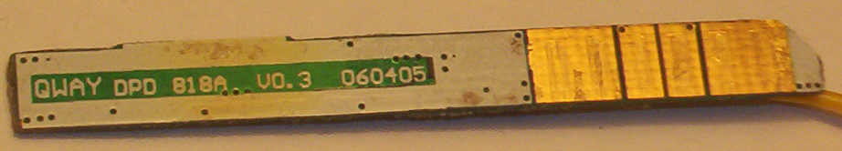
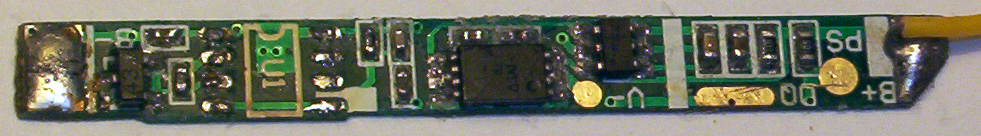
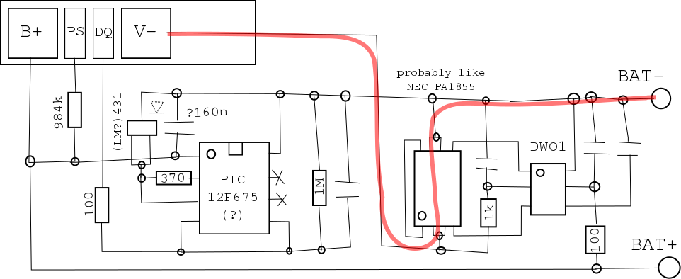
These values are approximated and there may be mistakes in the PCB reverse engineering (the PCB was melted into a plastic case). On the picture the U1 chip (PIC) has been desoldered (caused the short circuits).
The CPLD chip (Xilinx CoolRunner-II [9]) serves for the peripheral power control (sound, GSM, backlight, SD/MMC power, ...). A partial description is at the xda-developers wiki [10]. A better description is in the linux kernel [11]. Bits related to the charging are (first value: register address = 0x0c000000+val*4, second value: bit offset):
EGPIO_MAGICIAN_BQ24022_ISET2, which switches between the 100mA ("0") and 500mA ("1") charging currents.
EGPIO_MAGICIAN_CABLE_STATE_AC, which indicates a connected USB charger (to an electric outlet).
EGPIO_MAGICIAN_CABLE_STATE_USB, which indicates a connected USB cable to a computer.
The last GPIO is named GPIO30_MAGICIAN_BQ24022_nCHARGE_EN, which is a pin of the PXA SoC (not the CPLD). This pin is just a master enable for the charging.
The LCD backlight should be realised by a chip marked with "5A986 1521E". Chip is probably the Monolithic Power Systems MP1521 [12], the package is a same and some pins look like they are connected in the compatible way. Anyway, the backlight is realised by the PWM0 routed to the PXA GPIO16. By the way, the Intel PXA27x manual [13] (section 24.4.2.1) shows the pin 16 is multiplexed between PWM and FFUART, so we can theoretically modulate the backlight by the serial port . I tried, but I think there is a low-pass filter, which erases any signals sent by the FFUART. Another way to control the backlight is setting the pin to be permanently on or off (using the pin 16 as a GPIO). The function multiplexing is described in the section 24.5 of [13].
When using the PWM on the pin 16, we need to set a correct frequency. The MP1521 datasheet [12] says we can set anything between 100 and 400Hz, but from my tests it seems that this value is not always bulletproof. The PWM controller in the PXA27x have three registers: the frequency prescaling, period and a duty cycle settings. The period register should have the highest value, so we can have the smoothest duty cycle steps. The frequency is then set by the prescaler. It seems this approach is same in the linux kernel. The frequency settings are in the platform definition (still not in the vanilla kernel, because I still need patches for the peripherals around to be acknowledged first) [14].
While the backlight can be controlled by the PWM from the PXA, there is another control. In the CPLD we can set two additional GPIOs: EGPIO_MAGICIAN_BL_POWER, which can disable the backlight completely and EGPIO_MAGICIAN_BL_POWER2 which works like the overdrive. After the EGPIO_MAGICIAN_BL_POWER2 is set, the maximum brightness level will be increased.
These controls are combined in the platform code [14] (but not yet calibrated), so you can just use:
#black
	echo 0 > /sys/class/backlight/pwm-backlight/brightness
#full brightness
	echo 272 > /sys/class/backlight/pwm-backlight/brightness
The brightness does not works from zero value and it exhibits some hysteresis.
In the next section I will write about compiling the distribution.
If you like this howto or you want the author to try other crazy stuff with the Magician, you can donate the bitcoins to: 1FV88JF4DDBR7XBbssRyC4aqrA3vNkzM86  .
.
[1] DS2760 datasheet
[4] Voltage table drivers/cpufreq/pxa2xx-cpufreq.c
[5] drivers/input/touchscreen/ads7846.c
[6] Datasheets ADS7846 TSC2046
[9] Xilinx CoolRunner-II DS093 XC2C128
[10] CPLD wiki
[12] MP1521 datasheet
[13] Intel PXA27x Processor Family Developer’s Manual
[14] Magician platform definition
Tiskni
Sdílej:
![]()
![]()
![]()
![]()
![]()
![]()
 9.3.2015 20:30
Bedňa | skóre: 34
| blog: Žumpa
| Horňany
.
10.3.2015 08:50
Bedňa | skóre: 34
| blog: Žumpa
| Horňany
9.3.2015 20:30
Bedňa | skóre: 34
| blog: Žumpa
| Horňany
.
10.3.2015 08:50
Bedňa | skóre: 34
| blog: Žumpa
| Horňany
 Asi mi išlo o to čo má GPIO nejakú ochranu proti preťaženiu.
).
10.3.2015 18:43
Bedňa | skóre: 34
| blog: Žumpa
| Horňany
OK, teším sa na ďalší dieľ.
.
10.3.2015 22:00
Bedňa | skóre: 34
| blog: Žumpa
| Horňany
Grammar nazi to som ja
Asi mi išlo o to čo má GPIO nejakú ochranu proti preťaženiu.
).
10.3.2015 18:43
Bedňa | skóre: 34
| blog: Žumpa
| Horňany
OK, teším sa na ďalší dieľ.
.
10.3.2015 22:00
Bedňa | skóre: 34
| blog: Žumpa
| Horňany
Grammar nazi to som ja
ISSN 1214-1267, (c) 1999-2007 Stickfish s.r.o.