HollowByte je zranitelnost typu Denial of Service (DoS) v kryptografické knihovně OpenSSL. Útočník může odesíláním škodlivého payloadu o velikosti pouhých 11 bajtů zaplnit paměť serveru. OpenSSL před ověřením dat vyhradí nepřiměřený blok paměti (až 131 KB). Server pak čeká na data, která nepřišla. Zranitelnost je opravena ve verzích OpenSSL 4.0.1, 3.6.3, 3.5.7, 3.4.6 a 3.0.21.
Ve španělské A Coruñě probíhá GUADEC 2026, tj. letošní konference vývojářů a uživatelů desktopového prostředí GNOME. Videozáznamy přednášek jsou k dispozici na YouTube.
Společnost Collabora ve spolupráci s Valve vyvíjí Holo Core, tj. port Arch Linuxu pro ARM64 procesory (AArch64), který bude pohánět VR headset Steam Frame. Pro testování Arch Linuxu pro AArch64 jsou k dispozici binární balíčky, zdrojové kódy i kontejner pro Docker nebo Podman.
Mikroprocesor Zilog Z80 byl oficiálně uveden na trh před 50 lety, tj. v červenci 1976. Výroba mikroprocesoru skončila v roce 2024.
Výzkumníci ze společnosti ESET objevili 11 zapomenutých UEFI shim zavaděčů, které byly podepsány společností Microsoft, a které umožňují útočníkům obejít ochranu UEFI Secure Boot na většině zařízení. Microsoft je zneplatnil (přidal jejich hash do databáze dbx) v rámci aktualizace Patch Tuesday dne 9. června 2026. Uživatelé Linuxu mohou databází aktualizovat pomocí LVFS. Ověřit zneplatnění zavaděčů lze pomocí skriptu uefi-dbx-audit. Jedná se o CVE-2026-8863 a CVE-2026-10797.
pico-usb-wifi je open source firmware pro Raspberry Pi Pico W, který jej promění v USB Wi-Fi adaptér. Po připojení k počítači se objeví jako zařízení USB CDC-NCM.
Americká společnost Google ze skupiny Alphabet bude muset podle nových požadavků Evropské unie umožnit společnosti OpenAI i dalším konkurentům v oblasti umělé inteligence (AI) a internetových vyhledávačů přístup ke svým službám. Ve svém rozhodnutí o tom včera informovala Evropská komise (EK). Opatření má zajistit dodržování pravidel, jejichž cílem je omezit v EU tržní sílu velkých technologických firem. Google s tím nesouhlasí.
… více »Nové verze webových prohlížečů Chrome a Firefox jsou vydávány každé 4 týdny. Aktuální verze Chrome je 150. Aktuální verze Firefoxu je 152. V březnu bylo oznámeno, že od září přejde Chrome na dvoutýdenní cyklus vydávání verzí. To by znamenalo, že Chrome v číslování verzí Firefox brzy přeskočí. Vývojáři Firefoxu proto také od září přecházejí na dvoutýdenní cyklus vydávání verzí. :-)
Microsoft Comic Chat (Wikipedie), tj. grafický IRC klient z devadesátek, který převáděl konverzace na IRC do podoby komiksových panelů, a který zpopularizoval font Comic Sans, je dnešním dnem open source. Zdrojové kódy jsou k dispozici na GitHubu pod licencí MIT.
Byla vydána (𝕏) nová verze 26.7 open source firewallové a routovací platformy OPNsense (Wikipedie). Jedná se o fork pfSense postavený na FreeBSD. Kódový název OPNsense 26.7 je Xenial Xenops. Přehled novinek v příspěvku na fóru.
28.2.2015 12:15
| Přečteno: 2381×
| 
I2C in the magician seems to be used for three chips: the normal I2C for the camera and sound, the low speed I2C for core voltage control. The kernel has driver for them, but it seems it never worked! It is possible to emulate I2C with GPIO, which is very slow and driver eats too much CPU power when it is handling huge amount of data (eg. camera stream start or changing sound volume). So I have quickly decided to fix PXA I2C after some playing with camera drivers.
Main cause of incompatibility is Omnivision OV9640 camera module [3]. It communicates with SCCB protocol [4], which is basically I2C with some features omitted (possibly to evade I2C licensing  ). Problem is, that SCCB and I2C coexistence on same bus makes debugging hard as hell.
Main difference with I2C standard is that I2C device sends acknowledge handshake but SCCB device uses this cycle as "don't care" (and host must therefore ignore it). PXA I2C controller didn't support this "feature", so I needed to patch it (after strong debugging). Kernel I2C subsystem supports SCCB mode, so we just need to add flag I2C_M_IGNORE_NAK into platform data [5]. In the PXA I2C driver [6] we need to add statement to ignore NACK bit if this flag is set.
Second bug in PXA was forgotten I2C_M_STOP flag, which generates STOP state on the SCCB after any message, but START states were always generated and this START-STOP imbalance caused bus freezing when SCCB was used. Solution is simple: patching pxa-i2c driver with correct support for I2C_M_STOP and adding I2C_M_STOP flag to any SCCB driver (ov9640.c).
I sent patch for both bugs and patch should be in the vanilla kernel starting from 3.19 [11].
PXA I2C supports two speeds: 100kbps and 400kbps. It seems 400kbps is problematic and transmission is sometimes corrupted, but it was tested on damaged Magician, so it can be possible.
GPIO I2C driver requires setting pins 117 (SCL) and 118 (SDA) as Alternate Function 0 (GPIO) and as "output" in the magician platform definition [5]. I have modified GPIO driver [7] too, but it was for debugging PXA I2C controller, so I don't know if the modification is really required or not (and I don't want to test it anymore, because it is REALLY slow  ).
).
Second I2C bus (power I2C) has only one device, which is I2C compatible, so it works without any additional changes. Using GPIO I2C on it will probably need similar configuration.
Problem is, that with valid SCCB support in I2C PXA you cannot use i2c-tools [2] on SCCB device or else bus will go into frozen state (should be possible to reset by i2c_pxa module reload and reset of this device by corresponding reset GPIO). It is possible to force SCCB mode in PXA I2C driver [6] by forcing I2C_M_STOP flag for every transaction (hack). Another way is to add SCCB support into i2c-tools, but from my search it seems that i2c-tools using SMBUS (another clone of I2C) functions for injecting any I2C messages into bus, so it could mean rewriting part of i2c-tools. Maintainer of i2c-tools [2] is Jean Delvare, so anyone can send patches or feature requests to him.
Camera in my magician is from Omnivision and exact type is OV9640, but it seems [8] another phones with magician platform can have OV9650 [9]. They are practically compatible (only difference seems to be frame size, but I didn't examined OV9650 datasheet too closely). For driver debugging we can probably use OV9650 application note datasheet (registers are described more in detail), but many things were discovered without it.
It seems there are at least three versions of OV9640 datasheet. It look like a paradox, but older version have sometimes more information than the newer versions (it depends probably on camera firmware version too).
One problem during magician reimplementation with OV9640 was faulty PXA I2C driver (which was fixed by using OV9640 ), so I could not verify if reset GPIO (57, active in one) and power GPIO (116, active in zero) works correctly. Other problem during testing was clock signal, which is enabled only when the camera is used by v4l2 (and I2C on OV9640 only with pixel clock active). So for testing purposes I have used shell scripts to be able communicate with unused camera.
	modprobe i2c-dev

	devmem 0x41300004 32 $((`devmem 0x41300004` | 0x01000000 ))   #enable clocks to Quick Capture controller

	devmem 0x40E00118 32 0x100000      #set GPIO116_MAGICIAN_nCAM_EN to "1"
	devmem 0x40E0001c 32 0x2000000     #set GPIO57_MAGICIAN_CAM_RESET to "1"

	devmem 0x40E00124 32 0x100000      #set GPIO116_MAGICIAN_nCAM_EN to "0"
	devmem 0x40E00028 32 0x2000000     #set GPIO57_MAGICIAN_CAM_RESET to "0"

	devmem 0x50000010 32 0x00880001    #enable pixel clock (unsafe write) in Quick Capture controller

	i2cget -y -f 0 0x30 0xa   #get Product ID MSB (=0x96), NOTICE i2c-tools ignore I2C_M_STOP
	i2cget -y -f 0 0x30 0xb   #get Product ID LSB (=0x49)
Register address for GPIO can be found in section "24.5.2 GPIO Pin-Output Set Registers (GPSR) and GPIO Pin-Output Clear Registers (GPCR)" of PXA27x datasheet [1]. QuickCapture controller clock control is described in section "27.5.5 Quick Capture Interface Control Register 4 (CICR4)". Master clock enable is in section "3.8.2.2 Clock Enable Register (CKEN)". Writing into these registers can make inconsistencies in drivers and lead to system freeze (more probably when V4L2 is operating simultaneously).
For hacking with power and reset signals of OV9640 module I measured pinout of this module (GPIO by GPIO toggling) and annotated it with the most possible (eg. AVDD) signals. Pins are numbered by numbers on module and should be same in image below. Voltages were measured with multimeter with weak battery, so real values are probably little lower  . Real voltages of approximated pins are in datasheets. Be warned, connector pin spacing are in sub-millimeter range .
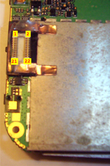
	~2.1V, DVDD?      22    21    3 Ohm to GND with power off
	RESET (gpio 57)   20    19    DD7
	DD6               18    17    DD5
	DD4               16    15    3 Ohm to GND with power off
	DD3               14    13    DD2
	DD1               12    11    DD0
	SCL               10    9     MCLK
	SDA                8    7     ~3.49V (same as datapins), (~40 kOhm to GND), DOVDD?
	3.0V, AVDD?        6    5     PCLK
	nPOWER (gpio116)   4    3     FV
	LV                 2    1     3 Ohm to GND with power off
This pinout can be theoretically used to create a module with another CCD chip or to connect some fast data (possibly video) to magician. CCD with integrated JPEG encoder can greatly enhance speed and frame size of recorded video. Only problem would be with different voltage levels.
Magician sound system based on the UDA1380 chip [10] is an insane design. Chip itself offers I2S and raw SPI interface. PXA272 offers AC97, I2S and SSP (SPI) interfaces. But for more fun, chip interface is divided into SSP for the playback part and I2S for the capture part. This design makes kernel driver debugging hard as hell.
The main problem with sound in the magician are the configuration structures and bug with DMA. There are some more, but they are not critical (swapped values in mixer etc.). First bug was solved with this patch [12]. It is just assignment of bad structure, but it made very weird behavior (and it took me patching almost every sound subsystem function to discover this, only to realize that this bug was already repaired in newer kernel ). Second, more serious bug is capture DMA, where driver wrongly uses auto-incrementation settings for playback. In this case data were written into single word sequentially from all registers after FIFO register. Patch is here [13], but patch for the driver initialization is still not reported, so sound will still not work in vanilla (I must clean my modifications to be acceptable by vanilla standard). It seems, that soundcard must be divided into two virtual soundcard because of I2S/SSP schism.
If someone wants to hack sound chip online, then there are some tips:
Default behavior in driver is to power off everything, so you must patch source code to let UDA chip stay in powered state (basically any bits in register 0x0 of UDA1380 I2C interface).
Reset (EGPIO_MAGICIAN_CODEC_RESET) and power (EGPIO_MAGICIAN_CODEC_POWER) must be correctly set and clocks must be enabled (configuration ".dac_clk = UDA1380_DAC_CLK_WSPLL"). UDA1380 can use clocks from capture and playback interface (which is fun, if they are using different controllers in PXA). Below is script to enabling power. EGPIO pins are described at xda wiki [14] or at LXR [15] (first value is register address, incremented by 4, second value is word size).
#unpowered state
	devmem 0x0c000004 8 $((`devmem 0x0c000004` | 0x20))    #UDA1380 RESET enable
	devmem 0x0c000004 8 $((`devmem 0x0c000004` & ~ 0x40))  #UDA1380 POWER disable

#powered state
	devmem 0x0c000004 8 $((`devmem 0x0c000004` | 0x40))    #UDA1380 POWER enable
	devmem 0x0c000004 8 $((`devmem 0x0c000004` & ~ 0x20))  #UDA1380 RESET disable
Clock enabling wasn't needed during hacking, but it can be done by setting registers described in [1] (I2S and SSP1). Just notice all possible clock routing and fact, that a bad clock configuration in UDA1380 can cause temporary I2C or UDA1380 freeze (resetable). It seems that I2C works even without running clocks (all sound drivers are not loaded).
Another tip is for reading and writing I2C. UDA1380 is from NXP (developer of I2C), so is fully compatible, so i2c-tools works here. You should be able to use command like this:
i2cget -y -f 0 0x18 0 w #bus=0, address=0x18, register=0, width=16bit
Just remember, i2c-tools report values with swapped lower and higher octet.
In next section I will write about power system of HTC Magician.
If you like this howto or you want author to try some other crazy stuff with Magician, you can donate some bitcoins to address 1FV88JF4DDBR7XBbssRyC4aqrA3vNkzM86 .
[1] Intel PXA27x Processor Family Developer’s Manual
[2] http://www.lm-sensors.org/wiki/I2CTools
[3] OV9640 datasheets http://aitendo3.sakura.ne.jp/aitendo_data/product_img/camera/OV9640/OV9640FBG_DS (1.1).pdf http://hwui.googlecode.com/svn/trunk/Camera/DATASHEET/CameraModule/OV/
[4] SCCB Specifications - OmniVision
[5] arch/arm/mach-pxa/magician.c
[6] drivers/i2c/busses/i2c-pxa.c
[7] drivers/i2c/algos/i2c-algo-bit.c
[8] http://forum.xda-developers.com/showthread.php?p=3697908#post3697908
[9] ov9650 datasheets and application notes
[10] UDA1380
[11] http://lists.infradead.org/pipermail/linux-arm-kernel/2014-November/305783.html
[13] http://www.spinics.net/linux/fedora/linux-sound/msg00530.html
[14] http://forum.xda-developers.com/wiki/MagicianCPLD
[15] arch/arm/mach-pxa/include/mach/magician.h
Tiskni
Sdílej:
![]()
![]()
![]()
![]()
![]()
![]()
 1.3.2015 11:40
vlastikroot | skóre: 24
| blog: vlastikovo
| Milevsko
Není ten hardware dneska i na nějaké hraní příliš outdated?
a chci zkusit, zda to zvládnu celý. Samozřejmě velká část věcí se dá přenést na novější telefon (třeba takový GTAxx jsou skvělí, ale stojej příšerně moc).
1.3.2015 11:40
vlastikroot | skóre: 24
| blog: vlastikovo
| Milevsko
Není ten hardware dneska i na nějaké hraní příliš outdated?
a chci zkusit, zda to zvládnu celý. Samozřejmě velká část věcí se dá přenést na novější telefon (třeba takový GTAxx jsou skvělí, ale stojej příšerně moc).
 , stejně tak stavba věty je spíš česká. Jenže když se budu soustředit na gramatiku a sestavovat slovo po slovu, tak z toho bude technický blábol (což je možná už i teď ). Jinak ono by se to časem mělo zlepšovat (právě bych si na tomhle návodu rád trénoval psaní v angličtině).
.
, stejně tak stavba věty je spíš česká. Jenže když se budu soustředit na gramatiku a sestavovat slovo po slovu, tak z toho bude technický blábol (což je možná už i teď ). Jinak ono by se to časem mělo zlepšovat (právě bych si na tomhle návodu rád trénoval psaní v angličtině).
.
 AbcLinuxu.cz
 ITBiz.cz
 HDmag.cz
 AbcPráce.cz